Components
Introduction
This manual describes how to assemble a functional pHMeter once the PCB plate has been ready and the pieces for the casing have been laser cutted.
Assembling the casing
The first step to assemble the pHMeter is to put the casing together. In this part.
First, identify the parts you are dealing with. In the following image are shown all the parts required to build it.
note
Sections A and B are all the laser cut pieces for pHMeter.
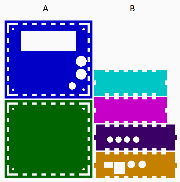
| A | DESCRIPTION |
|---|---|
| 1 | Top |
| 2 | Bottom |
| B | DESCRIPTION |
|---|---|
| 1 | Right |
| 2 | Left |
| 3 | Behind |
| 4 | Front |
Tape all parts together and please beware of the following details:
caution
- On the
Toppart, the 1 medium and 2 big circular holes designed for rotary push button and BNC connectors, respectively, should be on theFrontwhen looking from the front of the pHMeter. - The part containing only four medium circular holes for the pump
Behindshould be on the right side when you are looking from the front and the holes should be in the back. - On the
Frontpart, the 2 medium circular holes should be on the right side when you are looking from the front.